Testing standard

ISO 14270

Resistance welding — Destructive testing of welds — Specimen dimensions and procedure for mechanized peel testing resistance spot, seam and embossed projection welds

Written and technically reviewed by Dak System Inc. engineeringLast reviewed

ISO 14270 opens a resistance spot, seam or embossed projection weld progressively from one edge on a testing machine, and reports the peel force. It is the harshest of the three standard spot-weld loadings and the most sensitive to a brittle or undersized nugget. The current edition is ISO 14270:2016, reviewed and confirmed in 2021.

At a glance

Test type
Peel & adhesiona bonded joint is pulled apart
Published by
ISO
Edition
ISO 14270:2016

What the test does

A lap joint containing one spot, seam or embossed projection weld is made from two sheets whose free ends are bent away from each other. Those bent flanges are clamped in the testing machine and drawn apart, so the joint is opened progressively from one edge rather than loaded all at once. The machine records the force through the whole separation, and the peel strength is taken from that record.

The word that matters in the title is *mechanized*. The workshop peel test — a chisel, a vice and a pair of pliers — is a different thing, covered by ISO 10447, and it produces a nugget diameter rather than a force. This method puts the same action on a testing machine so the result is a measurement.

What it measures, and why it matters

Peel is the harshest of the three standard spot-weld loadings. Tensile shear pulls along the plane of the sheets, cross tension pulls straight through them, and peel concentrates the whole load on a moving line at the edge of the nugget. A weld that survives peel has margin everywhere else, which is why the method is used on joints that will see prying or crash loads rather than steady in-plane shear.

It is also the most sensitive of the three to coating and to nugget quality. A brittle nugget, a partially fused ring or an interfacial defect shows in the peel record before it shows in a shear figure, because the peel front finds the weakest part of the weld circumference and follows it.

Specimen, and the warning in the scope

The scope carries an explicit caution about weld diameter that changes how the result must be reported. It is easy to miss and it matters.

Joint
One spot, seam or embossed projection weld in overlapping sheets
Material
Any metallic material
Sheet thickness
0.5 mm to 3 mmLower than the 10 mm ISO 14273 allows, because thicker sheet will not bend into a peel flange without yielding.
Maximum weld diameter
7√t, with t the sheet thickness in mm
Recommended width is designed for
Welds of 5√t or lessBetween 5√t and 7√t the standard states the peel values obtained may be lower than expected, because the recommended specimen width was not sized for a nugget that large.
Flanges
Free ends bent away from each other before test
Bend the flanges without cracking the sheet
DakA cracked or unevenly bent flange starts the peel on one side, and the asymmetry is in the record before the weld has been touched.

Report the weld diameter with every peel force. Between 5√t and 7√t the figures are valid within the method but are not comparable with results on smaller welds, and a table of peel forces with no diameters against them cannot be interpreted afterwards.

Rate, and what is recorded

Loading
Continuous separation of the two flanges
Rate
As specified in the standard; not publicly quotableThe rate sits in the purchased text. Fix it and keep it constant across a comparison set.
Recorded
The whole force trace through the separation, not a single instant
Reported
Peel strength, plus the failure mode and the weld diameter
Log continuously
DakA peel is a progressive event. A logger sampling slowly enough to miss the shape of the trace loses the information that separates a clean nugget from a defective one.

Reading the peel record

Peel strength

Taken from the recorded force through the separation

A force, not a stress. As with the other spot-weld methods there is no defensible area to divide by.

Why peel is the harshest loading

The load is concentrated on a moving line at the nugget edge

Tensile shear spreads the load across the joint; peel does not. A weld that survives peel has margin in the other two directions.

What the trace shape shows

The peel front follows the weakest part of the weld circumference

A brittle nugget, a partially fused ring or an interfacial defect shows here before it shows in a shear figure.

How the test runs

  1. 01Weld the coupons on the schedule under test.
  2. 02Cut the specimens to the tabulated width and overlap.
  3. 03Bend the free end of each sheet away from the other to form the flanges.
  4. 04Check both flanges are bent to the same angle and neither has cracked.
  5. 05Measure and record sheet thickness and weld diameter.
  6. 06Clamp one flange in each grip, close to the bend.
  7. 07Separate the flanges continuously at the specified rate.
  8. 08Record the force through the whole separation.
  9. 09Examine the failed weld and classify the failure mode.
  10. 10Report peel strength, failure mode and weld diameter together.

Gripping too far from the bend lets the flange straighten under load. Part of the crosshead travel then goes into unbending the specimen rather than opening the weld, and the early part of the trace describes the sheet instead of the joint.

Grips and fixtures for this method

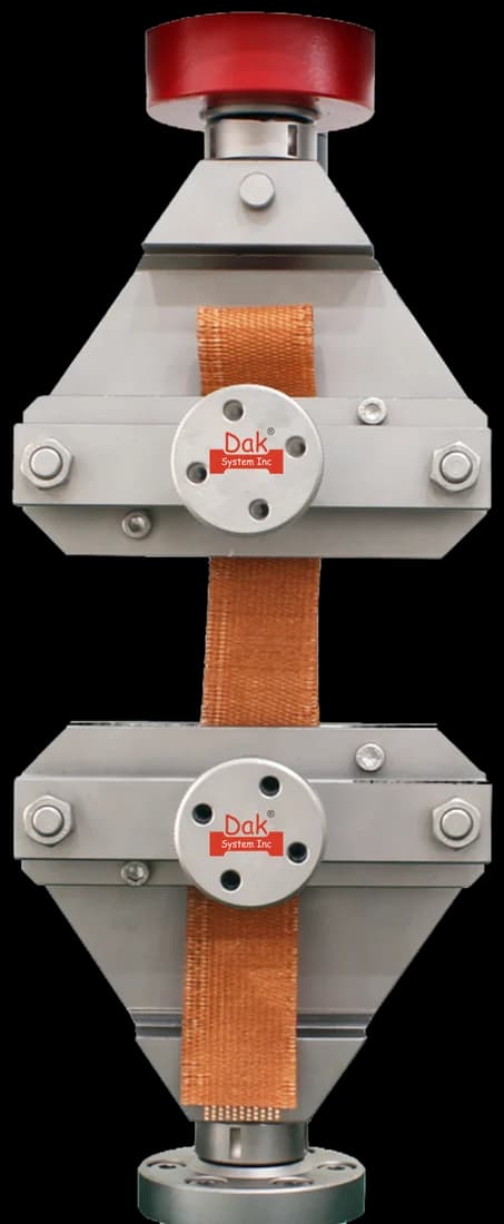
100 mm wide vice action grips holding a woven belt specimen
Two face setsTJ-26

100mm Wide Vice Action Grips

The flanges are short and have to be clamped near the bend. A wide vice-action face takes the full specimen width in one clamped area without the specimen pulling free as the peel front advances.

Specifications
Self-identifying

Load Cells

Peel forces on thin sheet run from a few hundred newtons to a few kilonewtons — far below the shear force on the same joint. A load cell sized for the joint rather than the frame is what makes the trace readable.

Specifications

What the report has to contain

  • Reference to ISO 14270 and the edition
  • Parent material, grade, coating and thickness of both sheets
  • Welding parameters used to make the joint
  • Specimen width, overlap and flange length
  • Weld diameter, and whether it lies between 5√t and 7√t
  • Test rate
  • Peel strength for each specimen
  • Failure mode for each specimen
  • Mean and the number of specimens
  • Any departure from the tabulated geometry, and why

What the machine must be capable of

Peel forces are far lower than shear forces on the same joint — commonly a few hundred newtons to a few kilonewtons on thin automotive sheet. Capacity is not the problem; resolution is. A 5 to 50 kN frame with a load cell sized for the joint rather than for the frame is the sensible arrangement, with force accuracy to ISO 7500-1 Class 1.

Because the result is taken from a force record over the whole separation and not from a single instant, the machine has to log continuously at a usable rate. Vice-action or wedge grips hold the bent flanges; the flanges are short, so the jaw faces need to grip near their edge without the specimen pulling free.

No extensometer is required. What matters is that the flanges stay symmetrically loaded as the peel front advances, which is a matter of clamping squarely rather than of instrumentation.

What goes wrong in practice

Flanges bent at unequal angles, or bent so sharply that the sheet has cracked, dominate the failure list. The peel then starts on one side and the record is asymmetric. Gripping too far from the bend lets the flange straighten under load, so part of the crosshead travel goes into unbending the specimen rather than opening the weld. And reporting a peel force without the weld diameter makes the result uncomparable, particularly in the 5√t to 7√t band the standard warns about.

Mechanised peel against the workshop peel test

They look like the same action and they answer different questions. Confusing them is the commonest misunderstanding on this method.

Mechanised peel (ISO 14270)Peel and chisel (ISO 10447)
Where it is doneOn a testing machineAt the bench, in a vice
ResultA peel force, recordedA nugget diameter, measured
PurposeQuantify joint qualityConfirm a nugget formed and size it
RepeatableYes, within the methodOperator-dependent by design
Substitutes for the otherNoNo

A production line that peels welds with a chisel every hour is doing ISO 10447, not ISO 14270, and cannot report a peel force from it. Both are legitimate; only one produces a measurement.

Questions we are asked about this test

What is ISO 14270?

ISO 14270 is the international method for mechanized peel testing of resistance spot, seam and embossed projection welds. The free ends of the two sheets are bent away from each other, clamped, and drawn apart so the weld is opened progressively from one edge while the force is recorded. The current edition is ISO 14270:2016, which superseded the 2000 edition and was reviewed and confirmed in 2021.

How is it different from the peel test done with a chisel?

Completely, in purpose. The chisel-and-vice peel test is covered by ISO 10447 and is used on the shop floor to confirm a nugget formed and to measure its diameter; it is operator-dependent by design and produces no force. ISO 14270 puts the same opening action on a testing machine so that the output is a recorded peel force. A line peeling welds with a chisel every hour is doing ISO 10447 and cannot report an ISO 14270 result from it.

Why is the thickness range only 0.5 mm to 3 mm?

Because the specimen has to be bent into flanges before it is tested. Beyond about 3 mm the sheet will not take that bend without yielding, and a flange that has yielded is no longer a clamping tab — it is part of the deformation the machine is measuring. ISO 14273 covers up to 10 mm precisely because its specimen stays flat.

What is the warning about welds between 5√t and 7√t?

The scope allows welds up to 7√t in diameter, but the recommended specimen width was sized for welds of 5√t or less. The standard states that between those two limits the peel values obtained may be lower than expected, because the specimen is not wide enough for the nugget. The results remain valid within the method but are not comparable with results on smaller welds, so the weld diameter has to be reported with every force.

Why is peel the harshest of the three loadings?

Because the load is concentrated on a moving line at the edge of the nugget rather than spread across the joint. Tensile shear loads the weld in its strongest direction and cross tension pulls it apart uniformly; peel attacks the circumference and follows whichever part of it is weakest. That is also what makes it the most sensitive test to a brittle nugget, a partially fused ring or an interfacial defect.

What machine does it need?

A modest frame with good low-end resolution. Peel forces on thin automotive sheet run from a few hundred newtons to a few kilonewtons, so a 5 to 50 kN frame with a load cell chosen for the joint rather than the frame is the right arrangement, with force accuracy to ISO 7500-1 Class 1. Continuous logging matters more than capacity, because the result comes from the whole force trace and not from a single peak.

Do all three spot-weld tests need to be run?

Not always, but a joint characterised by only one of them is only partly characterised. ISO 14273 in tensile shear is the routine acceptance test, ISO 14272 in cross tension is what crash-relevant work needs, and ISO 14270 in peel is the most searching of the three. Where a specification names one, that is the one to run; where the question is whether a weld schedule is any good, all three say different things.


Running ISO 14270 on the Series 7200 and Series 9000

Dak verifies against whichever standard the method names, and where a class applies our frames sit a class tighter than it asks.

The method asks forDak supplies
CapacityA few hundred newtons to a few kN on thin automotive sheet — far below the shear force on the same jointLoad cells from 1 kg to 60 ton on the Series 7200, and 0.5 to 100 kN on the Series 9000
Force accuracyISO 7500-1 Class 1ISO 7500-1 Class 0.5 — a class tighter than the method asks
GrippingVice-action or wedge grips clamping the two bent flanges close to the bendOur vice-action grips or peel and adhesion fixtures, built to the specimen
EnvironmentAmbient laboratory conditions; no conditioning atmosphere is specified3009 series chambers, −150 °C to +400 °C — temperature only

This page describes the method as practised. The governing text is the current edition from the issuing body. Tell us what you are testing and we will answer with the machine, the fixture and a quotation.

Materials tested to it

The test it standardises

Other standards explained