
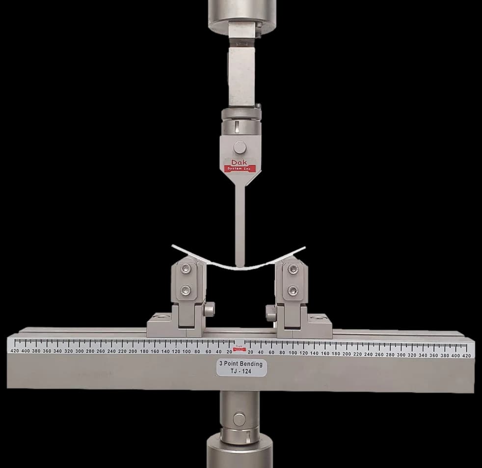
Adjustable spanTJ-124
Three Point Bend Fixture
A three-point bend fixture with adjustable span and the roller diameters the method specifies — span-to-depth ratio is set on the fixture, not assumed.
Specifications
Testing standard
Fibre-reinforced plastic composites — Determination of flexural properties
Written and technically reviewed by Dak System Inc. engineeringLast reviewed
ISO 14125 determines the flexural strength and modulus of a fibre-reinforced composite by bending a rectangular bar on two supports. The span-to-thickness ratio is the decision that matters: too short and the specimen fails in interlaminar shear instead of bending, and the number then describes the wrong property entirely.
From the test method to your testing system
Explore the DAK machines already listed for ISO 14125, then review the grips, measurement and setup requirements below.
 Universal Testing MachineSeries 7200Explore the machine →
 Universal Testing MachineSeries 9000Explore the machine →
01Understand the method
A rectangular bar from the laminate is placed on two supports set to a span calculated from its thickness — commonly sixteen times it. A loading nose descends at a rate chosen to give a specified strain rate at the outer surface, either at mid-span for three-point loading or at two points for four-point, and force is recorded against deflection until the specimen fails. Flexural stress comes from the force, the span and the section; strain from the deflection, the thickness and the span; the modulus from the slope over a defined strain range.
The outputs are flexural strength and flexural modulus. Bending is how many composite parts are actually loaded — panels, spars, leaf springs, blade shells — and because it loads the outer plies hardest while barely troubling the middle, it is unusually sensitive to how a laminate is stacked. That makes it a searching production control: a lay-up change, a cure problem or a resin-starved surface ply shows up here before it shows up in tension. It is also quick and needs no tabs, gauges or grips, which is why it is so widely specified.
02Prepare the specimen and test settings
Almost everything that goes wrong in composite flexure is a span problem. The ratio decides which failure you get.
Flexural strength is not a material property in the way tensile strength is. It depends on span, on roller radii and on the lay-up through the thickness, so it compares specimens tested identically and nothing else.
03Build the test setup on a DAK machine
Force to ISO 7500-1 Class 1 over a modest range, commonly a hundred newtons to a few kilonewtons, and a crosshead able to hold the rate the method derives from the specimen. The rule is a strain rate of 0,01 per minute — 1 % per minute — at the outer surface, so the speed is calculated as v = 0,01 × L² / 6h for three-point loading and 0,01 × L² / 4,7h for four-point, then set to whichever of the ten speeds the method tabulates comes nearest: 0,5, 1, 2, 5, 10, 20, 50, 100, 200 and 500 mm/min. Worked through on the preferred three-point specimens that gives 2 mm/min for Class I and Class II, on the 64 mm span and 4 mm thickness the method sets for them — the very figure the standard uses as its own example — 1 mm/min for Class III on a 40 mm span and 2 mm thickness, and 5 mm/min for Class IV on an 80 mm span and 2 mm thickness. Four-point spans are longer — 66, 45 and 81 mm — and the same arithmetic gives 2, 2 and 5 mm/min. A speed named in the standard for the material being tested takes precedence over the calculation. The fixture needs an adjustable span and the correct roller diameters. Where modulus is required rather than strength alone, a deflectometer reading mid-span deflection directly is worth having: crosshead travel includes the specimen sinking into the supports, the fixture flexing and the frame's compliance, all read as deflection and all depressing the modulus.
A three-point bend fixture with adjustable span and the roller diameters the method specifies — span-to-depth ratio is set on the fixture, not assumed.
Specifications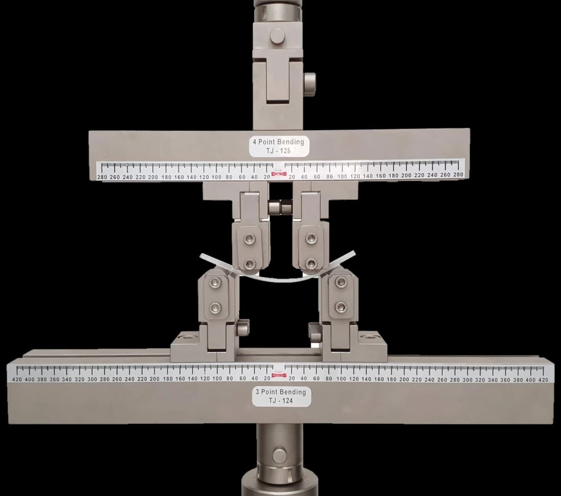
Four-point loading where the specification calls for it, putting a length of the specimen under constant moment rather than concentrating it under one nose.
SpecificationsDak verifies against whichever standard the method names, and where a class applies our frames sit a class tighter than it asks.
| The method asks for | Dak supplies | |
|---|---|---|
| Capacity | Low to moderate — commonly 100 N to 5 kN depending on lay-up and span | Load cells from 1 kg to 60 ton on the Series 7200, and 0.5 to 100 kN on the Series 9000 |
| Force accuracy | ISO 7500-1 Class 1 over the working range | ISO 7500-1 Class 0.5 — a class tighter than the method asks |
| Gripping | Three-point or four-point bend fixture with specified loading nose and support radii | Our bend fixtures, built to the specimen |
| Environment | 23 ± 2 °C standard laboratory atmosphere | 3009 series chambers, −150 °C to +400 °C — temperature only |
04Run the test
05Calculate, report and interpret
σf = 3 P L / (2 b h²)
For three-point loading. The four-point expression differs — using the three-point formula on four-point data is a common and invisible error.
εf = 6 s h / L²
Ef = Δσf / Δεf over the defined range
Nearly everything traces back to the span. A ratio too short delaminates the specimen and produces an interlaminar shear result labelled as a flexural strength — not a slightly wrong number but a measurement of another property, and it looks reasonable on the certificate. The second recurring error is taking the peak force from the wrong place: a delaminated composite often carries load again as the separated plies bear together, giving a second peak higher than the first, and only the first significant drop is the material failing. Using the three-point stress expression on four-point data is a third, and it is invisible in the result.
06Compare methods and find answers
| ISO 14125 | ASTM D7264 | |
|---|---|---|
| Geometry | Three-point and four-point | Three-point (Procedure A) and four-point (Procedure B) |
| Span ratio | Specified by material class | 16:1 default, adjustable |
| Rate basis | Outer-fibre strain rate | Outer-fibre strain rate |
| Used by | International and European specifications | North American specifications |
Close in intent and in the quantities reported. Span, roller radii and loading geometry all change a flexural number, so results transfer only when those match — the method actually run belongs on the certificate.
It is the ISO method for the flexural properties of fibre-reinforced plastic composites. A rectangular bar is supported on two rollers and loaded either at mid-span by a single nose or at two points, and the force-deflection record gives flexural strength and flexural modulus.
Because it decides which failure you get. On a short span the dominant stress between the plies is shear, and the specimen delaminates in its mid-plane before the outer fibres reach their limit — so the number you record is an interlaminar shear failure wearing a flexural label. A longer span lets bending dominate. Getting this wrong does not produce a slightly wrong flexural strength; it produces a measurement of a different property.
Not in the way tensile strength is. It depends on the span, on the roller radii and on how the lay-up is arranged through the thickness, because bending loads the outer plies hardest and barely troubles the middle. It is a genuinely useful comparative and quality-control figure, and it is not a value to feed into a design calculation as though it were intrinsic.
Because it puts a length of the specimen under constant bending moment rather than concentrating the maximum under a single nose. The failure then occurs at the weakest section within that length rather than wherever the nose happened to be, which is more representative of the material and avoids the local crushing a single nose can cause on a soft laminate.
Because crosshead travel includes the specimen sinking into the supports, the fixture flexing and the frame's own compliance. For a strength figure that hardly matters, since only the peak force is used. For a modulus it matters a great deal — every bit of that extra travel is read as specimen deflection and the modulus comes out low.
Reject it and check the span. A mid-plane delamination is an interlaminar shear failure, which means the span was too short for this laminate. Lengthening the span to the specified ratio usually moves the failure into bending. If it does not, the material genuinely has poor interlaminar strength — which is itself a finding, and one that ASTM D2344 short-beam strength is designed to quantify.
Because a composite that has delaminated will often carry load again as the separated plies bear on one another, producing a second peak higher than the first. That second peak is not a flexural strength — it is a broken specimen being pressed together. The first significant drop is where the material actually failed.
Discuss your specimen, test requirements and reporting needs with DAK engineering.
This page describes the method as practised. The governing text is the current edition from the issuing body. Tell us what you are testing and we will answer with the machine, the fixture and a quotation.